Xiamen Acey New Energy Technology Co.,Ltd
![$this->product_detail['product_name']](/uploadfile/category/db6e9c0d653a96dbd1612d6f8f719bdf.jpg)
Brand:
ACEYItem No.:
ACEY-BP24-200A300ACompliance:
CE CertifiedWarranty:
One Year warranty with lifetime supportOrder(Moq):
1Payment:
T/TProduct Origin:
ChinaLead Time:
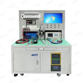
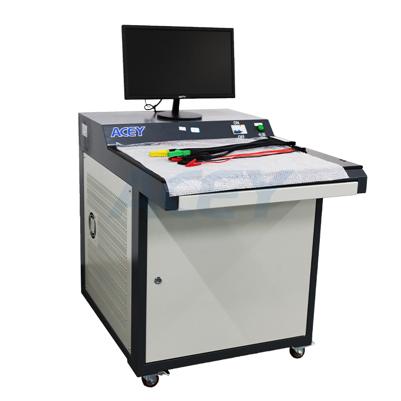
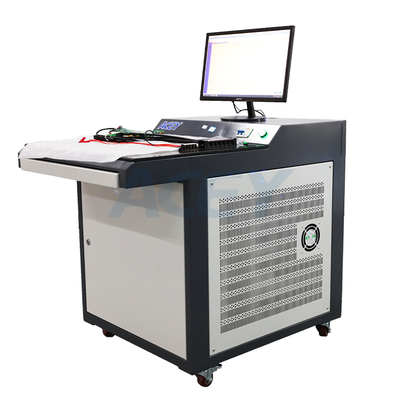
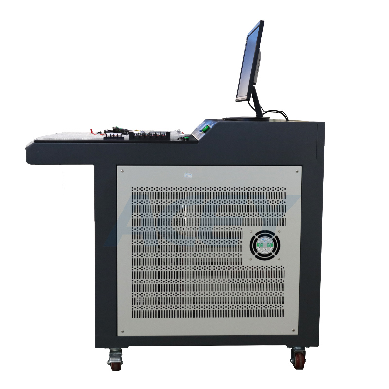
7days1-24 Series 200A Charge 300A Discharge BMS Tester Lithium Battery Protection Board Tester
Product Description
ACEY-BP24-200A300A battery management system tester features a high degree of automation, fast testing speed, and high testing accuracy. It has multiple test functions including overcharge protection, overcharge recovery, overdischarge protection, overdischarge recovery, overcurrent protection (overcharge current and overdischarge current), internal resistance, self-consumption, short circuit protection, overcharge protection time, overcurrent protection time, overdischarge protection time, balance current, and balance voltage. This tester can test the BMS of MCN battery, LiFeO4 battery, and cobalt acid battery. Moreover, it needs to be connected to a computer, and generally requires an XP system. The interface between the tester and the computer is RS232.
Parameter
1. Input power requirements: 180 ~ 240V 50/60HZ, power: 5000W
2. The equipment access to the power requirements of the domestic use of 220V/50HZ alternating current, allow fluctuations in the range of 10% or less.
3. Charging and discharging voltage: 5000mV ~ 160,000mV
4. The equipment can be used to detect and set the voltage range when charging or discharging.
5. Current accuracy: ±(0.1%FS+0.1%RD)
6. When the device detects or sets the current, the error range, i.e. 0.1% of the full scale plus 0.1% of the reading error
7. Voltage accuracy: ± (0.1%FS+0.1%RD)
8. Equipment in the detection or setting voltage, the error range, that is, 0.1% of the full scale plus reading error 0.1%.
9. Current resolution: 1mA, the smallest unit used by the device when detecting or setting current.
10. Voltage resolution: 1mV, the smallest unit used when the device detects or sets the voltage.
11. Cycle: cycle times:1~9999 times
12. Using the programming, the number of times the device carries out an uninterrupted cycle of the various indicators of the protection board.
13. Log tracking
14. With log function, including testing the entire process of operation records, exception records, can be used to test the process of tracing.
15. Data processing, man-machine interface
16. Test data is saved in EXCEL file.
17. The RS232 interface is used for the interface between the device and the upper computer, which can ensure the stability and real-time data acquisition.
18. Accuracy calibration / software calibration
19 with a sweep start function
20.MES system connection
Test Functions
| No. | Function | Setting range | Testing accuracy | Unit |
| 1 | Single section self-consumption | 0--500 | ±0.1 | uA |
| 2 | Self-consumption | 0--5000 | ±1 | uA |
| 3 | Overcharge protection voltage | 500--5000 | ±1 | mV |
| 4 | Overcharge protection release voltage | 500--5000 | ±1 | mV |
| 5 | Overcharge protection delay time | 0--10000 | ±1 | mS |
| 6 | Over-discharge protection voltage | 500--5000 | ±1 | mV |
| 7 | Over-discharge protection release voltage | 500--5000 | ±1 | mV |
| 8 | Over-charge voltage protection delay time | 0--10000 | ±1 | mS |
| 9 | Overcharge current protection value | 0.1--200 | ±0.01 | A |
| 10 | Overcharge current protection delay time | 0--20000 | ±1 | mS |
| 11 | Over-discharge current protection value | 0.1--300 | ±0.01 | A |
| 12 | Over discharge current protection delay time | 0.1--20000 | ±1 | mS |
| 13 | Equalizing opening voltage | 500--5000 | ±1 | mV |
| 14 | Equalizing Current | 1--500 | ±1 | mA |
| 15 | Charging Aging Current | 0.1--120 | ±0.01 | A |
| 16 | Discharge Aging Current | 0.1--120 | ±0.01 | A |
| 17 | Charging aging time | 0--100 | ±1 | S |
| 18 | Discharge current aging time | 0--100 | ±1 | S |
| 19 | Single section self-consumption difference | 0-500 | ±0.1 | uA |
| 20 | Resistance | 0-999 | ±1 | m惟 |
| 21 | Short circuit protection time | 0--5000 | ±1 | uS |
| 22 | Charging aging voltage | 500--5000 | ±1 | mV |
| 23 | Single discharge aging voltage | 500--5000 | ±1 | mV |
| 24 | Open circuit voltage | 120000 | ±1 | mV |
| 25 | Number of voltage simulations | 24 | 0 | PCS |
Other technical parameters
| Item | Parameter Description |
| Consumption Current Measurement Range | 1 ~ 5000uA |
| Consumption current resolution | 0.1uA |
| Resistance | AC internal resistance:0-999mr |
| Protection time resolution: | overcurrent protection time: 0-999ms; short circuit protection time: 0-999us |
| 1 channel signal voltage output: | 500~5000mV |
| AD/DA bit | AD: 16bit DA: 16bit |
| Discharge mode | CC mode |
| 32 analog cores | Input/output 500~5000mV, voltage accuracy ±0.1% |
| Communication rate | 2-way SBS communication, communication rate 10~100Kbps |
| Other | One way voltage sampling, 0~5000mV, accuracy:±0.1% |
| Protection function | Global protection parameters (including reverse connection protection, voltage lower limit protection, voltage upper limit protection, current upper limit protection), CC charging protection parameters (abnormal voltage trend protection, abnormal charging current fluctuation protection, abnormal voltage fluctuation protection), CC discharge protection parameters (including abnormal voltage trend protection, abnormal discharge current fluctuation protection, abnormal voltage fluctuation protection) |
| Communication | The interface of the device adopts RS232/DB9 interface, and the communication rate is 38400, which can ensure the stability and real-time data acquisition. All communication ports of the device are isolated and have lightning protection design. |
| Circuit structure | Modular structure, available spare parts, spare parts for timely replacement and maintenance. |
| Equipment organization | Split cabinet structure |
| Safety level | Conforms to EN60950 and GB4943 requirements. |
| Noise | Test noise according to IEC62040-3 method, noise less than 70dBA. |
| The sound level meter used should meet the requirements of IEC804 Type I, and the accuracy should be better than ±0.5dB. | |
| Protection grade | IP20 |
| Cabinet color | Gray-white |
| Cabinet color | Gray-white |
| Lightning protection | Reach the 2-pole lightning protection requirement of GB17626. |
| Cooling | Forced air cooling, air outlet and air inlet to retain at least 20cm of space |
| Starting pulse voltage | The maximum allowable pulse voltage at the moment of equipment testing and starting the process is ≤ (set number of test strings * set voltage of single unit)*110%, T≤500uS; |
| Starting pulse current | The maximum allowable pulse current at the moment of equipment testing and starting overcurrent testing process is ≤ (set number of test strings * set single-unit voltage * 110%, T ≤ 500uS); T ≤ 1mS; |
| Wiring method | Adopt reliable spring crimping method, flexible disassembly and replacement. |
Product Display


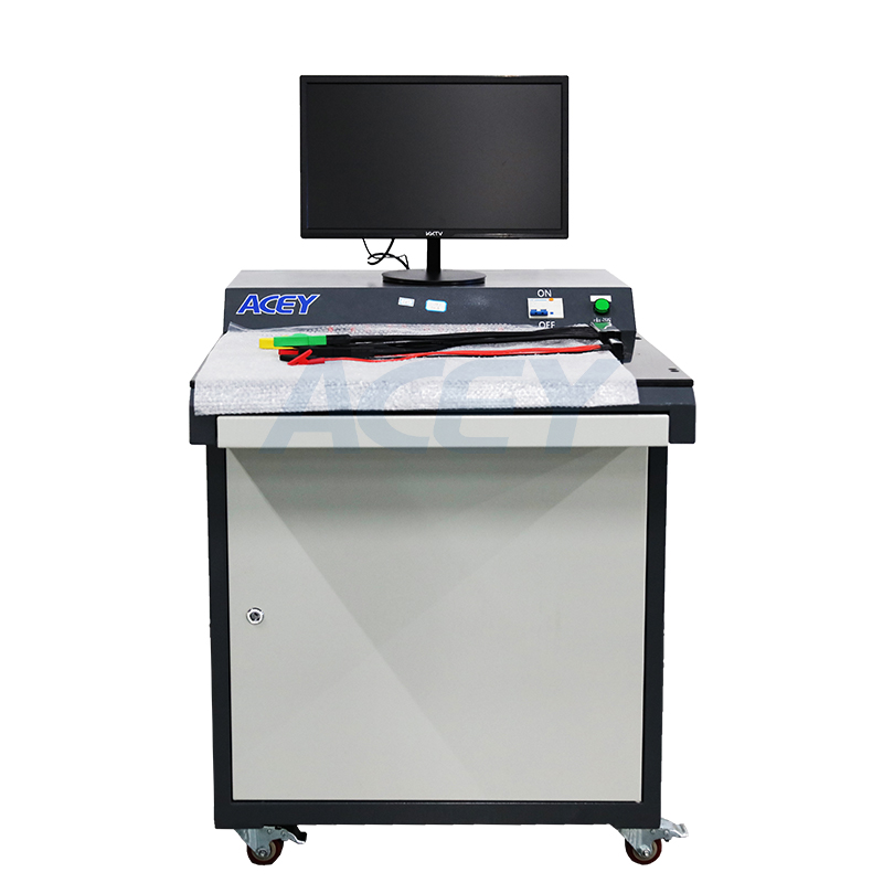
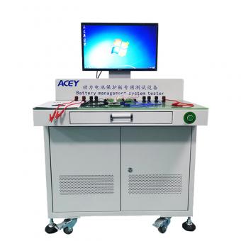
 1-24 Series 40A Charge 120A Discharge High Precision Lithium Battery Protection Board BMS Tester
ACEY-BMS24-120 can detect the function of the lithium battery protection board and various performance indicators, facilitate the debugging and development of samples, and provide a set of standards for rapid detection for R&D personnel.
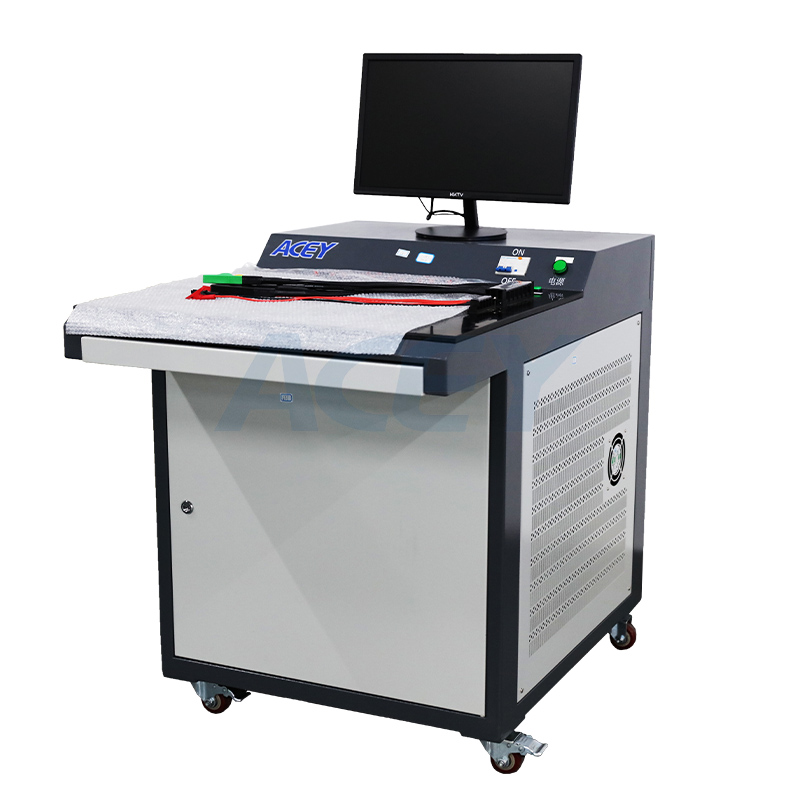
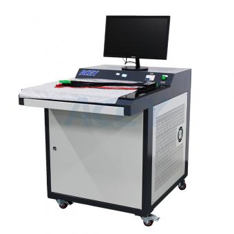
 24 Series 40A Charge 200A Discharge Battery Management System Protection Board BMS Tester
Battery protection board tester is used to test the performance and functionality of BMS. By using a battery protection board tester, manufacturers and users can ensure the quality and reliability of the protection boards, reducing the risk of battery failures and potential safety hazards.
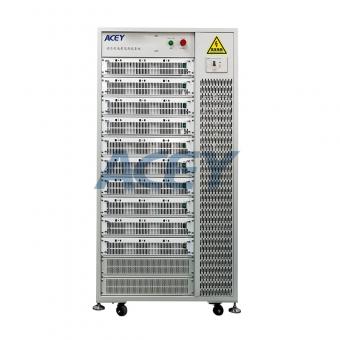
 1-32 Series 500A Charge 800A Discharge Battery Management System BMS Tester
BMS tester is used in the safety test of lithium battery protection board, to detect whether the functional indicators of the protection board are within the reasonable parameters.
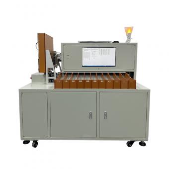
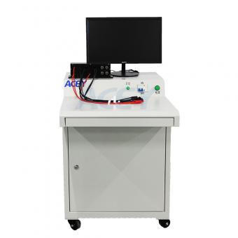
 1-32 Series 200A Charge 200A Discharge Battery Management System Tester Testing Machine
The lithium battery protection board tester is used for safety testing of lithium battery protection boards. It detects whether the functional indicators of the protection board are within reasonable parameters and provides workers with a set of testing standards, which is beneficial to improving production efficiency and facilitating quality control.
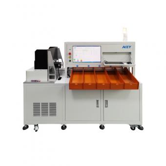
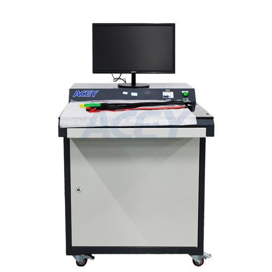
 1-24 Series 50A Charge 120A Discharge Bms Tester Machine
ACEY-BP24-50A120A BMS tester is used to test multiple functions of the protection board, including overcharge protection, overcharge recovery, overdischarge protection, overdischarge recovery, overcurrent protection (overcharge current and overdischarge current), internal resistance, self-consumption, short circuit protection, overcharge protection time, overcurrent protection time, overdischarge protection Time, balance current, balance voltage etc.
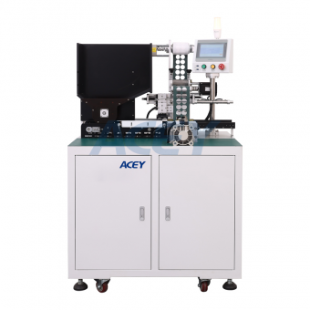
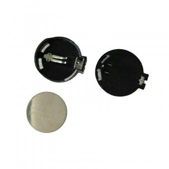
 Cylindrical Battery Pack Positive and Negative CCD Tester
CCD solder joint detector is an automatic equipment for lithium battery processing, which has the functions of automatic positive and negative pole detection, positive and negative solder joint detection, solder joint defect differentiation, automatic discharge, etc.
 100V 100A Charge 100A Discharge Energy-Saving Battery Aging Machine
ACEY-BA100100-8 battery pack test system with energy-saving function supports power down data protection and supports testing interruption caused by sudden power outage, communication interruption, or other abnormal reasons, and have automatic connection and continuation operation functions after the next condition is restored.
703, 7F, Zhonghengji Building, No.223, Qishan North Road, Huli District, Xiamen, Fujian, China
Email : allen@xmacey.com
Skype : tangrutian
Tel : +8618950009155
Whatsapp : +8618950009155